High voltage equipment could be exposed to transient overvoltages such as lightning impulse voltage or switching impulse voltage. It is important to test high voltage apparatus against those circumstances to prevent potential hazardous events and also to protect the high cost equipment. With these tests, we understand how to build a reliable system and an uninterrupted power supply. Let's start analyzing impulse voltages with the waveform of a full lightning impulse voltage.
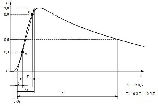
According to IEC60060-1 standard, this is a standard lightning impulse voltage with its time parameters depicted. It is shown on the graph that the wave rises rapidly to a peak value, then decreases to zero much more slowly. An impulse voltage has 3 main characteristics:
- Peak value
- Front time and
- Tail time or time to half value.
It's often hard to determine the exact starting point because of the external effects to the measuring system, therefore a virtual origin point is selected where the line from point A to point B intersects the time axis. A and B points are selected as 0.3 * Umax and 0.9 * Umax respectively. Front time is the time between the virtual origin and the point where line from A to B intersects Umax level. With using the notation on the graph, it is easily seen that T / 0.6 gives the front time value. Tail time is defined as the time from virtual point to the point where U equals to 0.5 * Umax. Impulse voltages are often denoted as 1.2/50 µs which means 1.2 µs front time and 50 µs tail time. Front time must be smaller than 20 µs to be defined as a lightning impulse voltage. These time parameters are important to achieve to be able to simulate real world conditions.
To be able to generate an impulse voltage with the given waveform, energy storing circuit elements should be used such as capacitors or inductors. These are the most commonly used one-stage impulse voltage generator circuits:
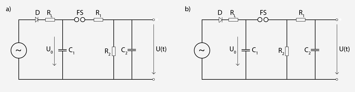
Basically, C1 capacitor is charged with direct current and discharged with the help of FS sphere gap over R1 and R2 resistors which shape the waveform according to their values. R1 is responsible for the front time and R2 for the tail time. U(t) output voltage is obtained across the C2 capacitor. To be able to understand the effects of the circuit elements to the waveshape, circuit equations can be solved in s domain with the help of laplace transform and then taking inverse laplace transform, the following equation can be obtained as the difference of two exponential functions:
Time constants α and β are roots of a quadratic equation with the circuit elements and they change with the circuit structure. Circuit a and circuit b have different time constants, different efficiencies in that matter.
Single stage impulse generators are used up to 300 kV. On the other hand, Marx generators can be constructed and generate up to 10 MV. A Marx generator circuit is as shown below:
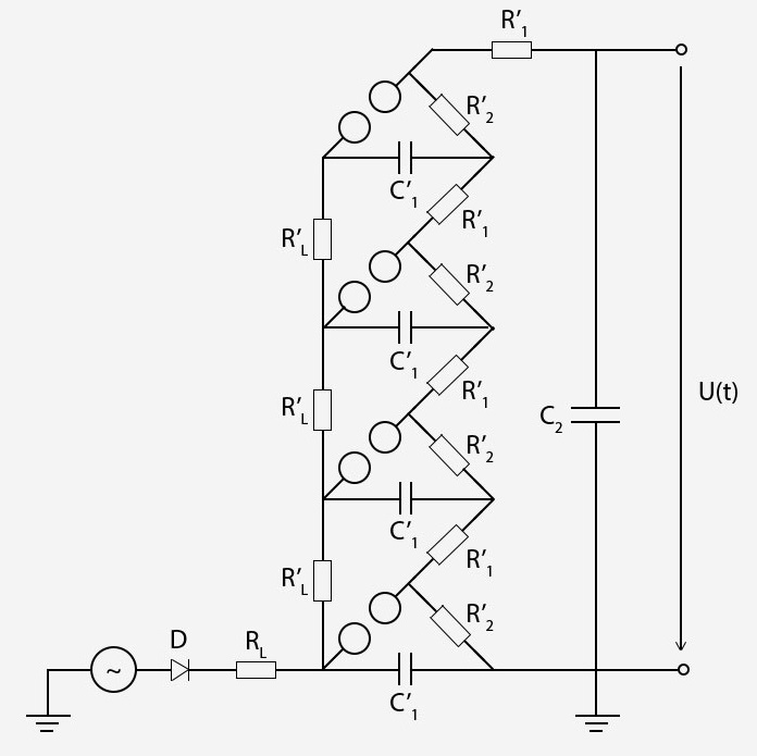
Marx generators consist of n identical stages. First, C'1 capacitors are slowly charged with U'0 in parallel, then with the help of spehere gaps they are suddenly connected in series. C2 capacitor is charged through R'1 resistors and discharged through R'1 and R'2 resistors. With this structure nU'0 voltage level is achieved. The test object and the impulse voltage measuring system are connected in parallel to the load capacitor C2. In comparison to the single stage generator, we have:
This is how enormous values of impulse voltages are achieved and paved the way of experiments with millions of voltages.
Procedure & Objective
Procedure
The simulator interface consists of a rough 3-D model of a 6 stage Marx generator, and six ranges as well as textboxes alongside them. It is possible to rotate, pan, zoom-in and zoom-out with mouse buttons on the 3-D model.
First, user determines the circuit parameters using ranges or textboxes. "Start the Experiment" button will lock the ranges and enable the "Charge Capacitors" button which will activate a progress bar to kind of imitate the slow charging of capacitors. When capacitors are charged, "Trigger Generator" button will be activated and it makes it possible to move spheres and connect capacitors in series.
Lastly, according to given circuit parameters, program will print out the impulse voltage waveform with the parameter values on top of it. The graph can be downloaded as an image, which allows users to conduct several experiments with the system and compare the end results.
Objective
The main objective with this experiment is to be able to comprehend the effects of the changing parameter values to the waveform of an impulse voltage. This is not easy to do in real life certainly. It would require strict safety precautions, supervision of an attendant and, moreover, big scale high voltage laboratories are very few in the world. The basic reason to build this system on a web site, is to make it accesible as much as possible in that matter. This system can be used by students who want to enhance their knowledge about the topic before the actual laboratory visit or who don't have an access to an actual lab but want to learn impulse voltages more deeply with the help of some visual elements involved.